| Instrumentation Cables | ||||||||||||||
![]() EN 50288-7 Instrumentation Cables
EN 50288-7 Instrumentation Cables
PE Insulated, LSZH Sheathed, CWB Screened Instrumentation Cables (Multipair)
RE-2Y(C)H 90°C / 300V
STANDARDS
Basic design to EN 50288-7
APPLICATION
These cables are used for transmission of analoge and digital signals in instrument and control systems at chemistry and
petr°Chemistry industry plants, power plants, natural gas and petroluem plants, etc...
These cables are used in the environments which have no corrosive gases are emitted in the event of fire. In case of fire, these cables inhibit the propagation of the flames whereby the development of smoke is extremely low. Instrumentation
cables are not allowed for direct connection to a low impedance sources, e.g. public mains electricity supply. With blue
sheath it is suitable for intrinsically safe systems. These cables are not recommended for direct burial. They are for indoor
and outdoor installation, in dry and wet l°Cations; on racks, trays, in conduits.
FIRE PERFORMANCE
| Flame Retardance (Single Vertical Wire Test) | EN 60332-1-2; IEC 60332-1-2; BS EN 60332-1-2; VDE 0482-332-1; NBN C 30-004 (cat. F1); NF C32-070-2.1(C2); CEI 20-35/1-2; EN 50265-2-1*; DIN VDE 0482-265-2-1* |
| Reduced Fire Propagation (Vertically-mounted bundled wires & cable test) | EN 60332-3-24 (cat. C); IEC 60332-3-24; BS EN 60332-3-24; VDE 0482-332-3; NBN C 30-004 (cat. F2); NF C32-070-2.2(C1); CEI 20-22/3-4; EN 50266-2-4*; DIN VDE 0482-266-2-4 |
| Halogen Free | IEC 60754-1; EN 50267-2-1; DIN VDE 0482-267-2-1; CEI 20-37/2-1 ; BS 6425-1* |
| No Corrosive Gas Emission | IEC 60754-2; EN 50267-2-2; DIN VDE 0482-267-2-2; CEI 20-37/2-2 ; BS 6425-2* |
| Minimum Smoke Emission | IEC 61034-1&2; EN 61034 -1&2; DIN VDE 0482-1034-1&2; CEI 20-37/3-1&2; EN 50268-1&2*; BS 7622-1&2* |
| No Toxic gases | NES 02-713; NF C 20-454 |
| Sunlight Resistance | UL 1581 section 1200 |
| Oil Resistance | ICEA S-73-532** |
Note: Asterisk * denotes superseded standard, **Test temperature +60°C, duration 4h. Retention: min 60% of tensite strength/min.60% of elongation.
VOLTAGE RATING
300V
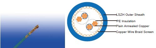
CABLE CONSTRUCTION
Conductor: Annealed copper solid or plain copper stranded to IEC 60228 Class 2.
Insulation: PE compound, EN 50290. 2-23.
Pair:Two conductors twisted to form a pair
Lay-up: Pairs laid up in layers of optimum pitch
Separator: Polyester tape
Overall Screen: Tinned copper wire braid
Outer Sheath: Thermoplastic LSZH compound type to EN 50290-2-27.
COLOUR CODE
Insulation: Black / White, continuously numbered on white core(1, 2..)for multipair.
Outer Sheath: Black or blue for intrinsically safe systems
Physical AND THERMAL PROPERTIES
Temperature Range During Operation (Fixed State): -30°C – +70°C
Temperature Range During Installation (Mobile State): -5°C – +50°C
Minimum Bending Radius: 7.5 X Overall Diameter
CONSTRUCTION PARAMETERS
| Caledonian Cable Code | RE-2Y(C)H | ||
| No. of Pairsx2xCross Section |
Copper Weight |
Approx. Weight | |
|
No.x2xmm2 | Kg/km | Kg/km |
| 0.5mm2, Multipair | |||
| RE-2Y(C)H 1P0.5 | 1x2x0.50 | 8.3 | 110 |
| RE-2Y(C)H 2P0.5 | 2x2x0.50 | 10.7 | 143 |
| RE-2Y(C)H 3P0.5 | 3x2x0.50 | 11.1 | 158 |
| RE-2Y(C)H 4P0.5 | 4x2x0.50 | 11.9 | 181 |
| RE-2Y(C)H 6P0.5 | 6x2x0.50 | 13.6 | 230 |
| RE-2Y(C)H 8P0.5 | 8x2x0.50 | 14.2 | 264 |
| RE-2Y(C)H 12P0.5 | 12x2x0.50 | 16.4 | 343 |
| RE-2Y(C)H 16P0.5 | 16x2x0.50 | 18.2 | 418 |
| RE-2Y(C)H 20P0.5 | 20x2x0.50 | 19.7 | 487 |
| RE-2Y(C)H 24P0.5 | 24x2x0.50 | 21.1 | 557 |
| 0.75mm2, Multipair | |||
| RE-2Y(C)H 1P0.75 | 1x2x0.75 | 8.7 | 119 |
| RE-2Y(C)H 2P0.75 | 2x2x0.75 | 11.4 | 161 |
| RE-2Y(C)H 3P0.75 | 3x2x0.75 | 11.9 | 185 |
| RE-2Y(C)H 4P0.75 | 4x2x0.75 | 12.7 | 214 |
| RE-2Y(C)H 6P0.75 | 6x2x0.75 | 14.6 | 278 |
| RE-2Y(C)H 8P0.75 | 8x2x0.75 | 15.4 | 324 |
| RE-2Y(C)H 12P0.75 | 12x2x0.75 | 17.8 | 427 |
| RE-2Y(C)H 16P0.75 | 16x2x0.75 | 19.8 | 526 |
| RE-2Y(C)H 20P0.75 | 20.x2x0.75 | 21.5 | 623 |
| RE-2Y(C)H 24P0.75 | 24x2x0.75 | 23.1 | 714 |
| 1.0mm2, Multipair | |||
| RE-2Y(C)H 1P1.0 | 1x2x1.0 | 9.4 | 1.3.5 |
| RE-2Y(C)H 2P1.0 | 2x2x1.0 | 12.3 | 184 |
| RE-2Y(C)H 3P1.0 | 3x2x1.0 | 12.8 | 214 |
| RE-2Y(C)H 4P1.0 | 4x2x1.0 | 13.7 | 251 |
| RE-2Y(C)H 6P1.0 | 6x2x1.0 | 15.6 | 326 |
| RE-2Y(C)H 8P1.0 | 8x2x1.0 | 16.4 | 382 |
| RE-2Y(C)H 12P1.0 | 12x2x1.0 | 19.0 | 511 |
| RE-2Y(C)H 16P1.0 | 16x2x1.0 | 21.2 | 636 |
| RE-2Y(C)H 20P1.0 | 20.x2x1.0 | 23.5 | 775 |
| RE-2Y(C)H 24P1.0 | 24x2x1.0 | 25.3 | 892 |
| 1.3mm2, Multipair | |||
| RE-2Y(C)H 1P1.3 | 1x2x1.3 | 9.7 | 140 |
| RE-2Y(C)H 2P1.3 | 2x2x1.3 | 12.9 | 204 |
| RE-2Y(C)H 3P1.3 | 3x2x1.3 | 13.5 | 242 |
| RE-2Y(C)H 4P1.3 | 4x2x1.3 | 14.5 | 285 |
| RE-2Y(C)H 6P1.3 | 6x2x1.3 | 16.7 | 375 |
| RE-2Y(C)H 8P1.3 | 8x2x1.3 | 17.4 | 444 |
| RE-2Y(C)H 12P1.3 | 12x2x1.3 | 20.2 | 599 |
| RE-2Y(C)H 16P1.3 | 16x2x1.3 | 22.6 | 750 |
| RE-2Y(C)H 20P1.3 | 20.x2x1.3 | 25.1 | 916 |
| RE-2Y(C)H 24P1.3 | 24x2x1.3 | 27.0 | 1064 |
Note : Other conductor sizes & core configurations are available upon request
Electrical PROPERTIES
| Conductor Area Size | mm 2 | 0.5 | 0.75 | 1.0 | 1.3 | 1.5 | |
| Insulation thickness (nominal) | mm | 0.4 | 0.4 | 0.4 | 0.45 | 0.45 | |
| Conductor resistance (20°C) | Ω/km | 36.7 | 25 | 18.5 | 14.2 | 12.3 | |
| Insulation resistance (20°C) | MΩ.km(Min.) | 5000 | |||||
| Mutual Capacitance (1 kHz) | pF/m(Max.) | ||||||
| ≤ 4 pairs | 115 | 115 | 115 | 120 | 120 | ||
| all other pairs | 90 | 90 | 90 | 105 | 105 | ||
| Capacitance unbalance(1 kHz) | pF/500 m (Max.) | 500 | |||||
| L / R (ratio) (max.) | μH/Ω | 25 | 25 | 25 | 40 | 40 | |
| Operating voltage Urms | V | 300 | 300 | 300 | 300 | 300 | |
| Test Voltage | Core to Core | V | 1500 | 1500 | 1500 | 1500 | 1500 |
| Core to Screen | V | 1500 | 1500 | 1500 | 1500 | 1500 | |